Geometry and numerical model of a piezo-controlled and a standard
2D wing section (page1 of 4)


“Think of an airplane as a great body with its end structures (wings, horizontal tail
surfaces, vertical tail surfaces) that could have the possibility to change their shape as
they had internal nerve endings and muscles ...”


Patches nomenclature for the NACA 0012
wing section
TOPIC 2
Areoelastic
analysis
Sketch of deformed grid: Case 7
(NACA 0012 wing section)
Deformed shape of NACA 0012 wing
section: Case 7, α = 0 deg (FSI results)
Cp fields and velocity fields: Case 0 and Case 7 h = 0 m,
α = 2 deg. FSI results (NACA 0012 wing section)
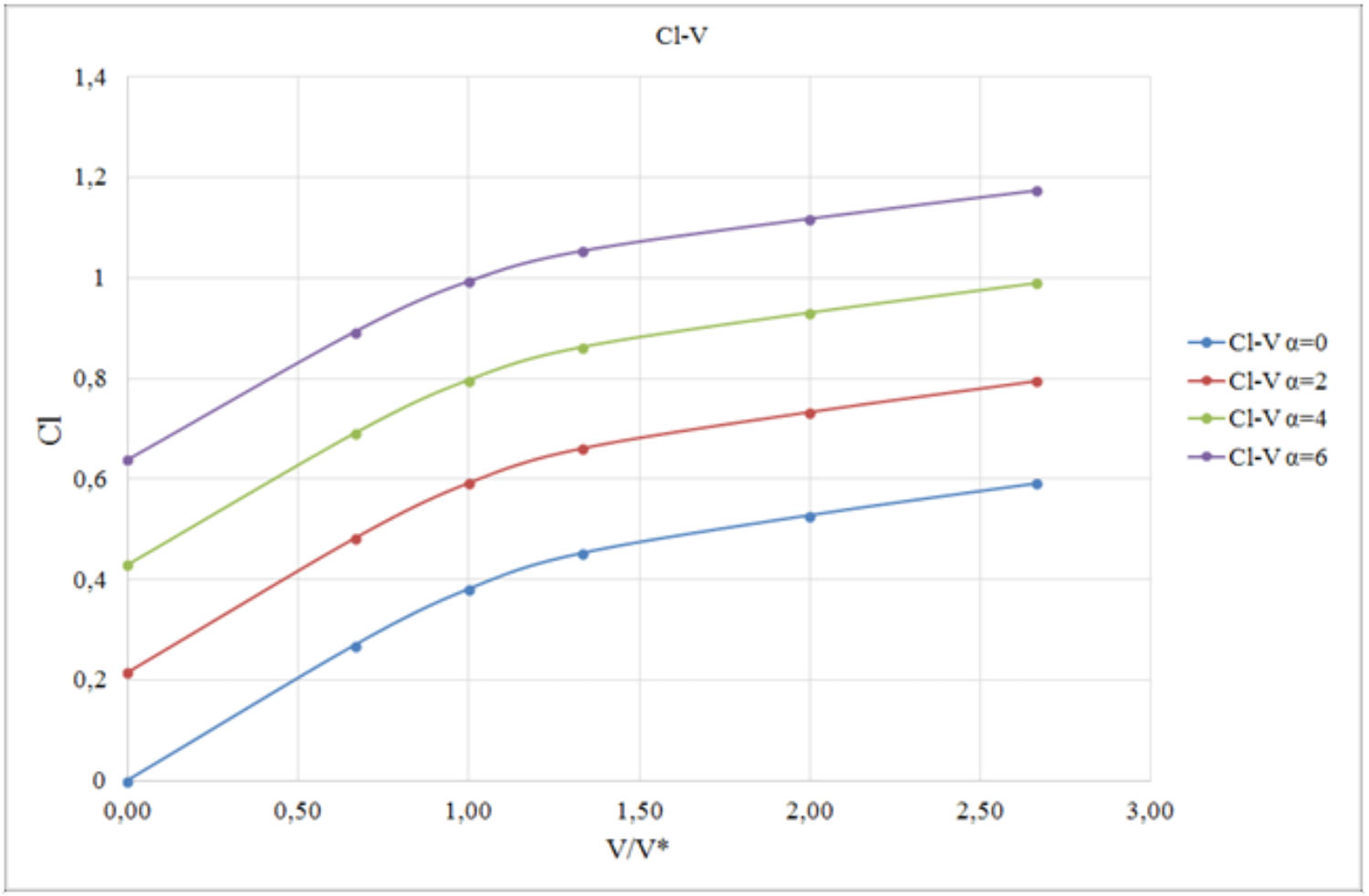
Cl-V/V* curves (NACA 0012 wing section)
vs. reference voltage V* = 900 V